Quick reference
These quick rows show the chart’s metric hex-head references. Each is a current reference—verify the applicable standard and manufacturer drawing.
Printable reference + builder
Use this bolt size chart to compare nominal thread diameter, metric pitch or inch threads per inch, and current hex-head wrench and tap-drill references. Start with the thread, not the head: an M10 label describes a nominal 10 mm thread, while a 17 mm wrench reference describes the current row’s hex head across flats. Those fields answer different questions.
This reference covers metric and SAE hex-bolt lookup only. Head dimensions, wrench openings, tap drills and clearance holes can change with the governing standard, edition, head style, manufacturer, material and required fit. Confirm the specification for the fastener and joint before ordering, drilling, tightening or substituting a part. The chart does not establish torque, strength, interchangeability or structural suitability.
Quick answer
Quick reference
These quick rows show the chart’s metric hex-head references. Each is a current reference—verify the applicable standard and manufacturer drawing.
M6
6 mm nominal thread, 1.0 mm common coarse pitch, 10 mm wrench and 5.0 mm tap drill. M8: 8 mm nominal thread, 1.25 mm pitch, 13 mm wrench and 6.8 mm tap drill. M10: 10 mm nominal thread, 1.5 mm pitch, 17 mm wrench and 8.5 mm tap drill. M12: 12 mm nominal thread, 1.75 mm pitch, 19 mm wrench and 10.2 mm tap drill.
Do not infer a universal head width from nominal diameter. Measure the actual head across flats and verify the drawing before selecting a wrench or socket.
Choose metric, SAE or a comparison view, then select the fields needed for the task. Keep diameter, pitch or TPI, head width, wrench opening, tap drill and clearance values in separate columns. Preview and export remain reference tools; generated files use the current quota and Terms and do not grant unrestricted redistribution or engineering approval. The builder includes hex-head data only. Socket-cap and carriage-head values require separate, verified references and cannot be inferred from hex rows.
Metric ISO • Metric • 1 page • portrait
ChartsPrintables.com
System: Metric (ISO) • Type: Hex Head • A4
| Size | Pitch (Coarse) | Pitch (Fine) | Head Width | Wrench Size |
|---|---|---|---|---|
| M3 | 0.5 mm | 0.35 mm | 5.5mm | 5.5mm |
| M4 | 0.7 mm | 0.5 mm | 7mm | 7mm |
| M5 | 0.8 mm | 0.5 mm | 8mm | 8mm |
| M6 | 1.0 mm | 0.75 mm | 10mm | 10mm |
| M8 | 1.25 mm | 1.0 mm | 13mm | 13mm |
| M10 | 1.5 mm | 1.25 mm | 17mm | 17mm |
| M12 | 1.75 mm | 1.5 mm | 19mm | 19mm |
| M14 | 2.0 mm | 1.5 mm | 22mm | 22mm |
| M16 | 2.0 mm | 1.5 mm | 24mm | 24mm |
| M18 | 2.5 mm | 1.5 mm | 27mm | 27mm |
| M20 | 2.5 mm | 1.5 mm | 30mm | 30mm |
| M22 | 2.5 mm | 1.5 mm | 32mm | 32mm |
| M24 | 3.0 mm | 2.0 mm | 36mm | 36mm |
| M27 | 3.0 mm | 2.0 mm | 41mm | 41mm |
| M30 | 3.5 mm | 2.0 mm | 46mm | 46mm |
| M33 | 3.5 mm | 2.0 mm | 50mm | 50mm |
| M36 | 4.0 mm | 3.0 mm | 55mm | 55mm |
Rows
17
System
Metric
PDF FILE SIZE
≈0KB
Quality
300 DPI
Export Set
One setup, every version you need.
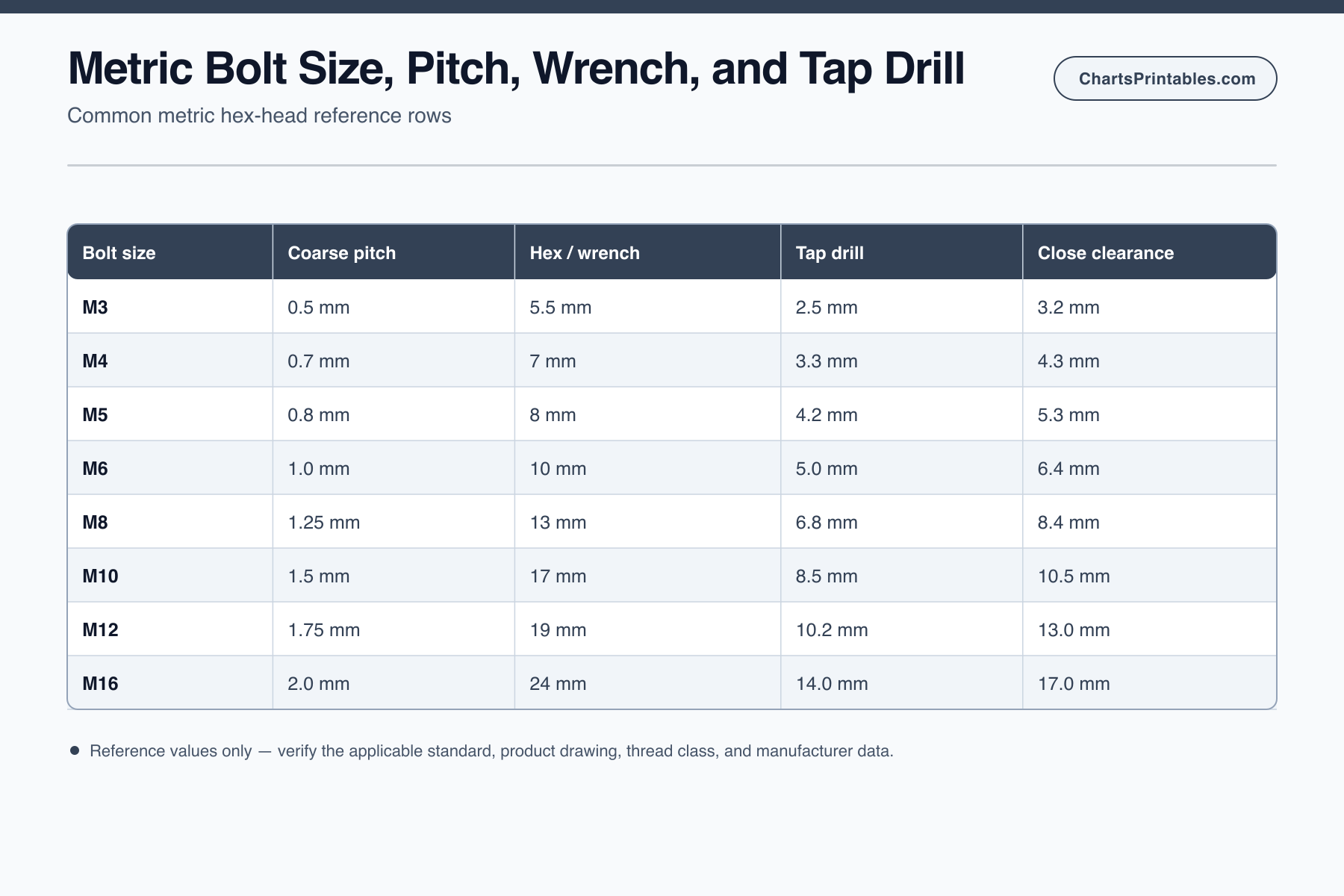
Visual quick reference
An M6 coarse-thread bolt uses a 1.0 mm pitch, a 10 mm hex wrench reference, and a common 5.0 mm tap drill.
The image keeps nominal bolt diameter, coarse pitch, hex-head wrench size, tap drill, and close-clearance values in one row. Use it as a quick lookup, then verify the standard, thread class, product drawing, and manufacturer data.
Fastener & Drill Pack
Seven focused, watermark-free references plus an index for bolts, screws, drill bits, nails, wrenches, tap drills and fastener markings.
USD 7 one-time · no subscription required
Place caliper jaws across opposite thread crests and read the major diameter. A measurement near 10 mm may point toward M10, but wear, coating and tool resolution mean the label still needs confirmation.
For metric threads, pitch is the crest-to-crest distance in millimeters. For inch threads, use a thread gauge or count threads per inch. Diameter alone cannot distinguish M10 × 1.5 from another M10 pitch, or 1/4-20 from 1/4-28.
The wrench opening follows head geometry, not thread diameter. This bolt size chart is limited to hex heads. Record the complete designation before comparing a tool, drill or replacement.
Compare the mating part or an identical approved fastener. Capture diameter, pitch, length, head style, property marking and coating. Use the bolt size chart to organize observations, not to approve a substitute.
Test pitch with a gauge and inspect thread condition. A listed tap-drill value describes the current reference row; it does not prove that an existing hole was cut to that percentage or that the material and tap call for the same drill.
Measure the hex head across opposite flats. If the listed reference and measured head disagree, stop and check the standard, edition, product drawing or manufacturer rather than assuming the thread label controls the head.
Number sizes such as #8 and #10 are thread designations, not decimal diameters printed in the name. Fractional sizes such as 1/4 inch name nominal major diameter. Keep that field separate from wrench openings and drill labels; a #7 tap drill is a drill-number label, not a #7 bolt.
A 1/4-20 label uses 20 TPI and commonly denotes UNC; 1/4-28 uses 28 TPI and commonly denotes UNF. They share nominal diameter but remain incompatible. Match the complete designation and specification.
The SAE part of this bolt size chart is not a cross-system substitution table. A nearby metric diameter does not establish equivalent pitch, thread form, fit, head, grade or load capacity.
Measure about 10 mm across thread crests, then confirm 1.5 mm between adjacent crests. The current metric hex row lists a 17 mm wrench and 8.5 mm tap-drill reference. Next verify head style, length, property marking, applicable standard and manufacturer information. This identifies a label; it does not approve the fastener, drill, torque or joint.
Measure a nominal 1/4-inch major diameter and confirm 20 TPI. The current imperial hex row lists a 7/16-inch wrench, #7 tap drill, 17/64-inch close-clearance reference and 9/32-inch free-clearance reference. Check thread series, head, fit and material. Do not transfer these values to 1/4-28 or another product.
Standards, editions, head styles, product series and manufacturers define different geometry. A wrench reference is a candidate, not a universal conversion from thread diameter.
Fit also depends on thread form, pitch, tolerance class, internal-thread condition, coating, clearance and the actual parts. Similar diameters do not establish interchangeability.
Head markings may indicate a class or grade, but do not replace the drawing, purchase specification, material certificate or joint design. This bolt size chart supplies no torque or strength guarantee. Structural, lifting, pressure, automotive and other safety-critical work requires the specified fastener and qualified review.
Method & limits
This bolt size chart separates nominal thread diameter, pitch or TPI, hex-head width, wrench opening, tap drill, and clearance references. Complete standard editions and field-level source records are not available for every numeric row, so verify the applicable standard, product drawing, and manufacturer data before use. Contact us if you find a value that needs correction.
Use the related workshop charts below to compare wrench openings, drill sizes, screw designations, and measured metric dimensions. They support adjacent tasks; none proves fastener compliance.
| Size | M-Bolt | S-Bolt |
|---|---|---|
| 8mm | M5 | 5/16" |
| 10mm | M6 | - |
| 7/16" | - | 1/4" |
| 13mm | M8 | - |
| 1/2" | - | 5/16" |
| 17mm | M10 | - |
| 9/16" | - | 3/8" |
| 19mm | M12 | 3/4" |
| 3/4" | - | 1/2" |
| Number | Fraction | Decimal (in) | Millimeters |
|---|---|---|---|
| #80 | — | 0.0135 | 0.34 |
| #50 | — | 0.0700 | 1.78 |
| #52 | 1/16" | 0.0625 | 1.59 |
| #41 | 3/32" | 0.0938 | 2.38 |
| #22 | 5/32" | 0.1562 | 3.97 |
| #11 | 3/16" | 0.1875 | 4.76 |
| #7 | 13/64" | 0.2031 | 5.16 |
| — | — | 0.2570 | 6.53 |
| — | 3/8" | 0.3750 | 9.53 |
| — | 1/2" | 0.5000 | 12.70 |
| Size | Pilot | Clear |
|---|---|---|
| #4 | 1/16" | 9/64" |
| #6 | 5/64" | 11/64" |
| #8 | 3/32" | 13/64" |
| #10 | 7/64" | 1/4" |
| #12 | 1/8" | 17/64" |
| 1/4" | - | F |
| 5/16" | - | P |
| 3/8" | - | W |
| M4 | 2.5mm | 4.5mm |
| M6 | 3.5mm | 6.6mm |
| Millimeters | Decimal (in) | Fraction (in) |
|---|---|---|
| 0.5 | 0.020 | 0 |
| 1 | 0.039 | 1/16 |
| 6.35 | 0.250 | 1/4 |
| 12.7 | 0.500 | 1/2 |
| 19 | 0.748 | 3/4 |
| 25.4 | 1.000 | 1 |
| 38.1 | 1.500 | 1 1/2 |
| 50.8 | 2.000 | 2 |
| 76.2 | 3.000 | 3 |
| 101.6 | 4.000 | 4 |
Start with nominal thread diameter, then confirm metric pitch or inch TPI. Check head style and across-flats wrench opening as separate fields. Verify the applicable standard, edition, manufacturer and fit before using a drill or tool reference.
No. M12 names a 12 mm nominal metric thread, while 1/2 inch equals 12.7 mm and uses an inch thread series. Similar diameter does not make pitch, form, head, fit or strength interchangeable.
Measure major diameter across opposite thread crests. For most external-head hex bolts, measure length from under the head to the tip. Confirm the product drawing when length controls fit.
Metric pitch is the millimeter distance between adjacent crests. TPI is the number of threads per inch on an inch-series thread. Both describe spacing, but are not interchangeable labels.
The wrench fits the head across flats, and geometry varies by standard, edition, head style, product series and manufacturer. Measure the actual head and check its specification.
No. This bolt size chart is a limited metric and SAE hex reference. Fit, torque and strength depend on the complete specification, materials, tolerances, joint design and installation. Use qualified guidance for safety-critical work.